Project Overview
This project is a custom PCB power distribution board designed for a competition robot.
The Problem: The robot required multiple regulated voltage rails (5V, 6V, 7.4V, 12V) stepped down from a single 18V tool battery. In compliance with safety regulations, an Emergency Stop (E-Stop) system was necessary to instantly cut power to motors and servos while preserving power to the onboard computer and sensors. Using discrete off-the-shelf modules resulted in hazardous wiring clutter.
The Solution: I engineered a monolithic PCB integrating 8x XL4015 buck converters alongside built-in E-Stop logic.
Technical Specifications
- Input Voltage: 18V (from power tool lithium battery)
- Output Channel Configuration:
- 5x 12V outputs
- 1x 7.4V output
- 1x 6V output
- 1x 5V output
- Rated Current: Up to 5A per channel (per XL4015 datasheet specifications)
- Measured Efficiency: Approximately 80% ~ 85%
- Core IC: 8x XL4015 Buck Regulators
- Safety Feature: Dedicated hardware E-Stop cutoff for high-power actuators.
Schematic & PCB Layout Design
Designing for multi-channel high current demanded strict trace width planning, copper polygon pouring, and via heat sinking. Initial unshielded inductors over continuous copper planes caused value shifts; switching to shielded inductors eliminated switching interference and delivered clean rail voltages.
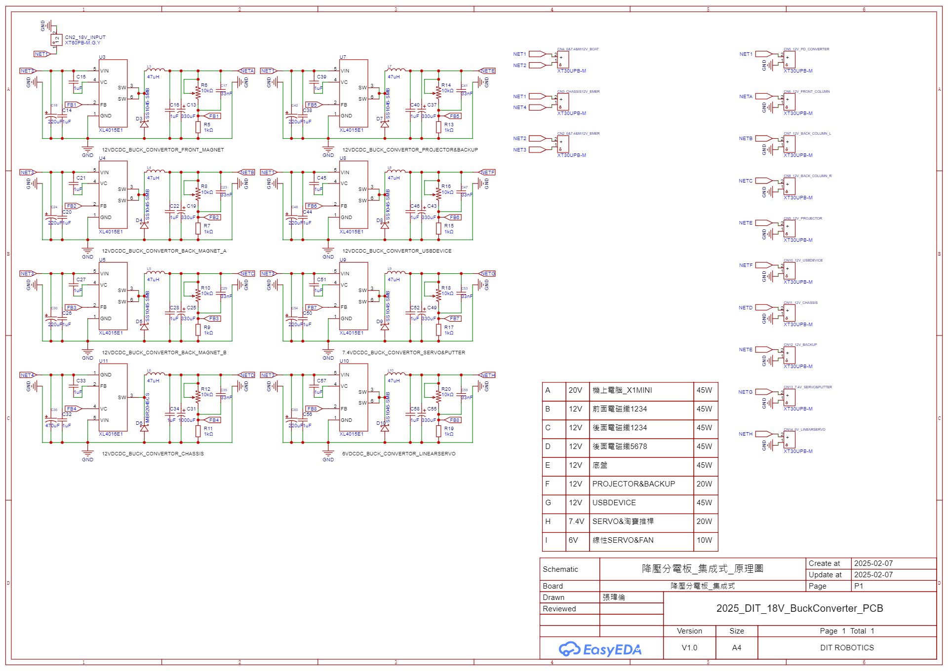
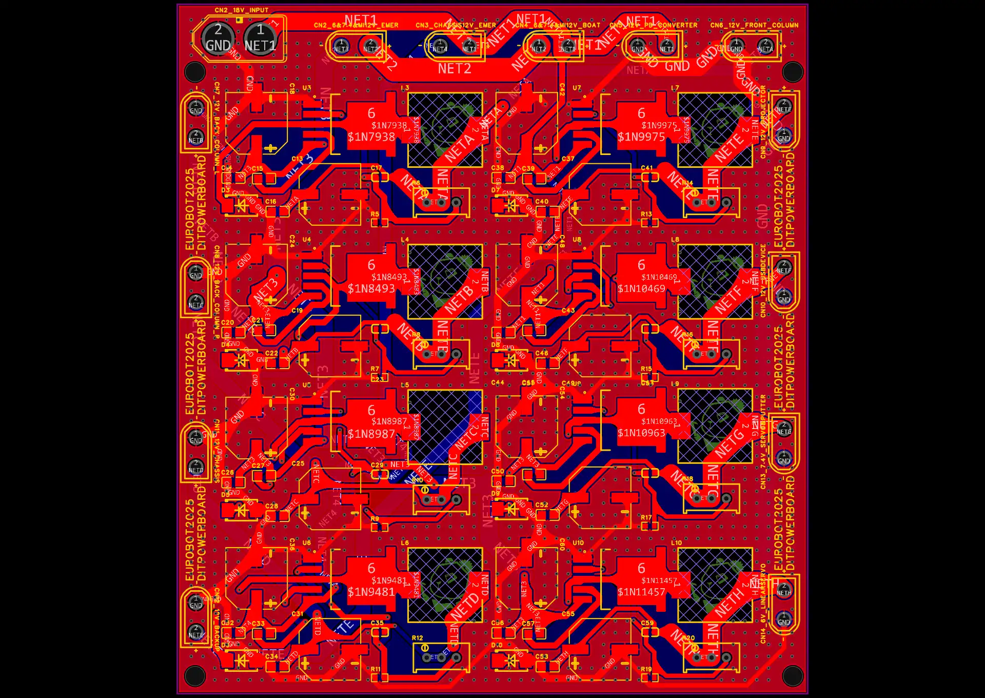
Click on any image above to open the full-screen PhotoSwipe lightbox for high-resolution inspection.
Fabrication & Chassis Installation
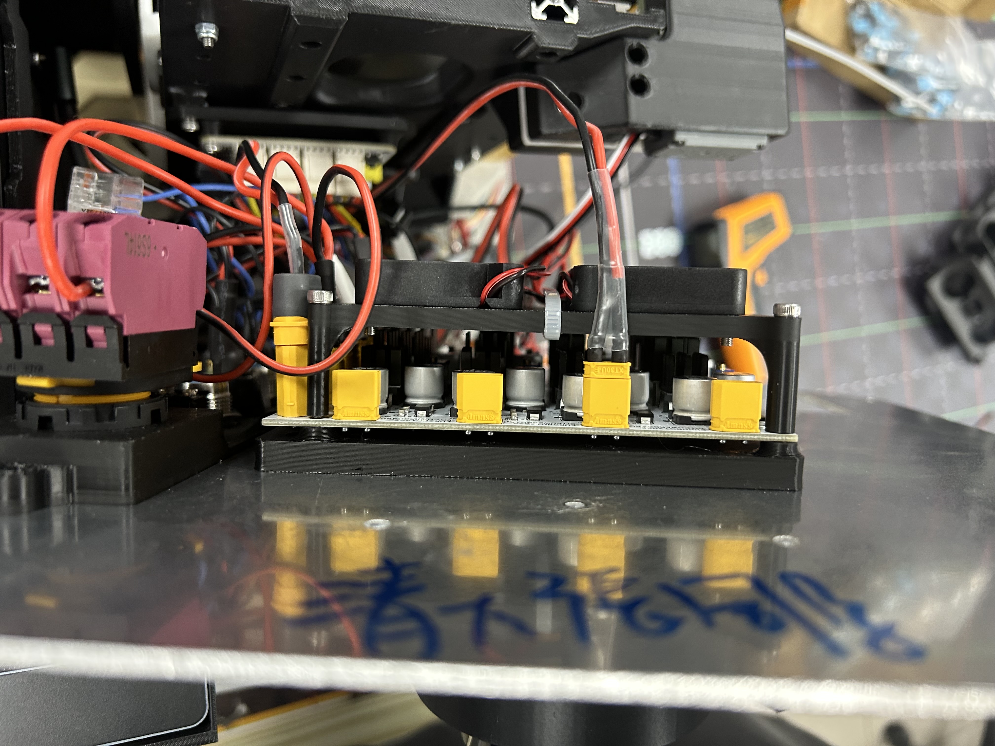
To guarantee solder reliability under heavy vibration, the board was professionally manufactured via JLCPCB PCBA (Surface Mount Assembly).
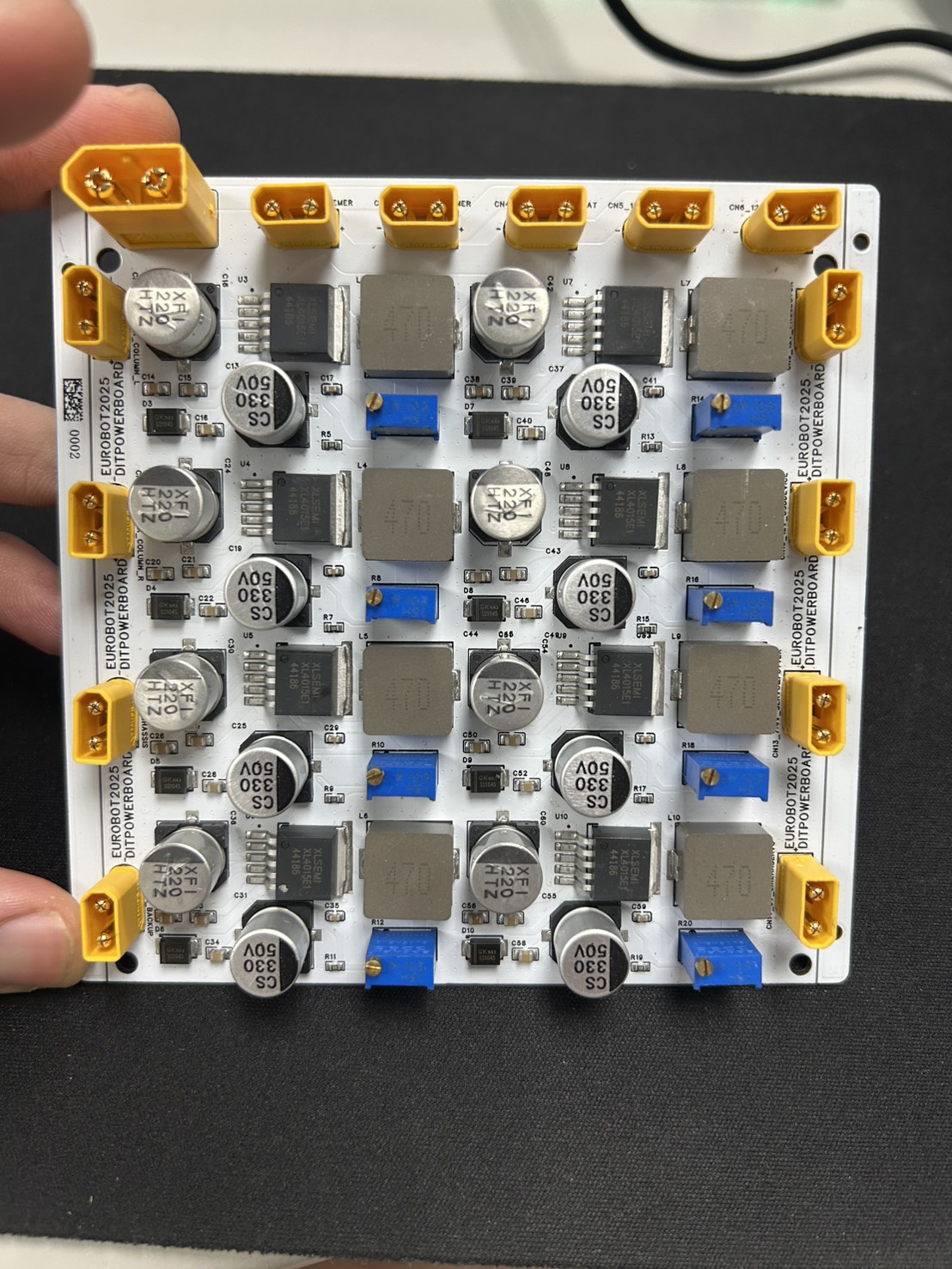
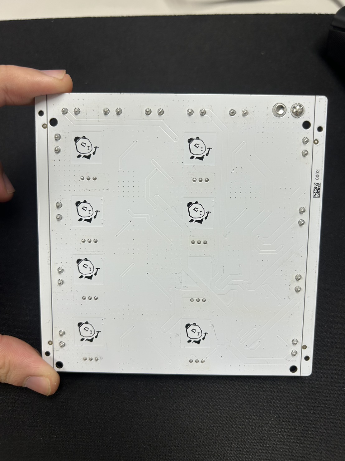
Verification & Future Improvements
- Performance: Stable output voltage regulation verified across load variations over 3 months of rigorous tournament testing.
- Thermal Management: Chip temperatures reached 80~90°C under full load, prompting the integration of an active cooling fan bracket.
- Functional Logic: E-Stop mechanism flawlessly isolates motor power without interrupting the master host computer.
Open Source Repository
The complete schematic and PCB layout design files (EasyEDA Pro) are open source:
- OSHWLab Repository: 18V-pcb Project Link