Project Overview
This project features a custom-designed robot chassis motion control board developed for the Eurobot international robotics competition.
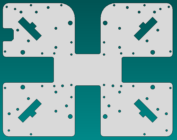
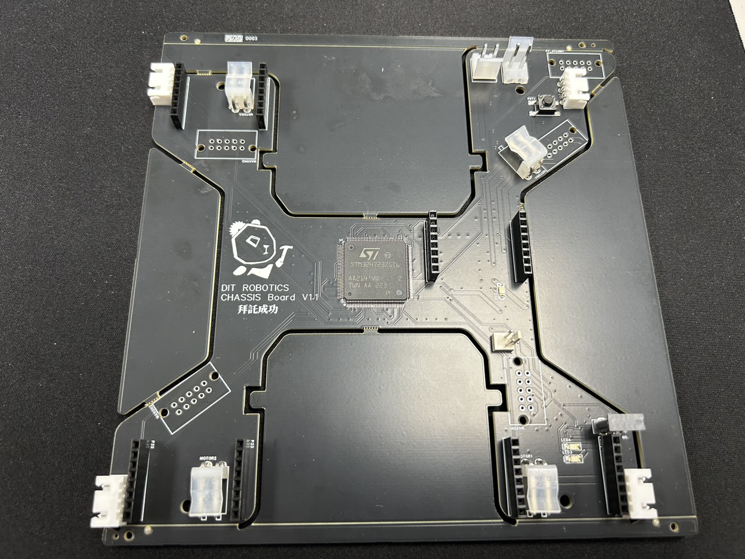
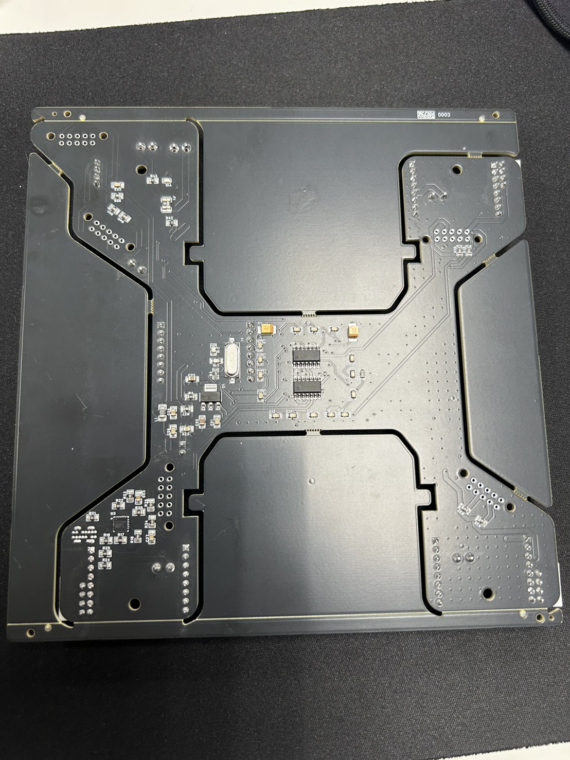
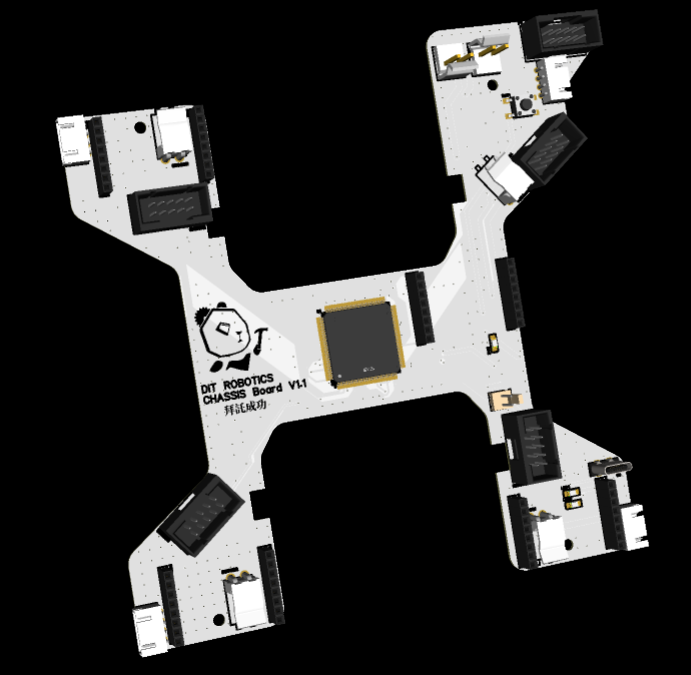
Previous robot generations relied on split architectures—separate logic boards paired with bulky external motor drivers. Facing severe spatial constraints inside the base chassis, I integrated logic processing, power distribution, and high-power motor drivers onto a single custom-contoured PCB, shaped to fit the chassis geometry seamlessly.
Technical Specifications & Architecture
- Microcontroller: STM32H723 (High-performance ARM Cortex-M7 with rich timer resources)
- Motor Drivers: Pololu G2 High-Power Motor Driver 18v17 (Sponsored by Pololu)
- Kinematic Topology: 4-wheel omnidirectional drive platform
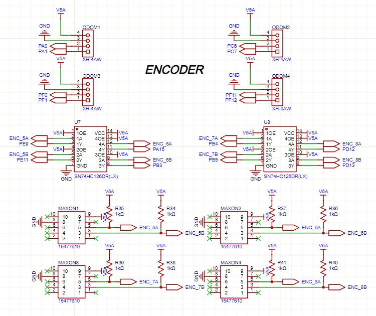
- Sensor Feedback: Real-time signal conditioning for 8 encoder streams (4x internal Maxon motor encoders + 4x external GoBilda odometry idler encoders)
Cross-Disciplinary CAD & PCB Integration
Designing an asymmetric, curved PCB contour inside basic EDA software is notoriously error-prone. To overcome this:
- I drafted the precise mechanical board outline and mounting clearance holes inside AutoCAD directly referencing chassis sheet metal models.
- The DWG geometry was imported into EasyEDA Pro as the master board boundary.
- High-current terminal blocks were positioned adjacent to motor mounts, reducing internal loose wire harness length by over 70%.
Click on any image above to open the full-screen PhotoSwipe lightbox for high-resolution inspection.
Engineering Challenge: Dual Encoder Signal Noise Management
A major technical obstacle lay in processing two divergent encoder signal types:
- Maxon Encoders: Required buffer circuits for clean logic level transformation.
- GoBilda Idler Encoders: Did not use external buffering and exhibited heightened vulnerability to switching noise.
Furthermore, several hardware timers on the STM32H723 share pin multiplexing with the ST-Link programming header. Through iterative oscilloscope probing, we strategically mapped the noise-resilient Maxon encoders to shared timer channels while reserving dedicated timers for high-precision GoBilda odometry, successfully achieving zero-loss pulse counting under rapid acceleration.
Hardware Fabrication & 3D Render
Communication & Competitive Results
- ROS Integration: Rather than waiting for stable microROS porting on the H723, we implemented
rosserialbridged from ROS1 into ROS2, providing stable bi-directional odometry telemetry and velocity commands. - Competition Performance: Flawlessly commanded the 4-wheel omnidirectional chassis through complex navigational maneuvers throughout the tournament.
Open Source Repository
The complete schematic and PCB layout design files are open source:
- OSHWLab Repository: 2025_dit_chassis_board Project Link